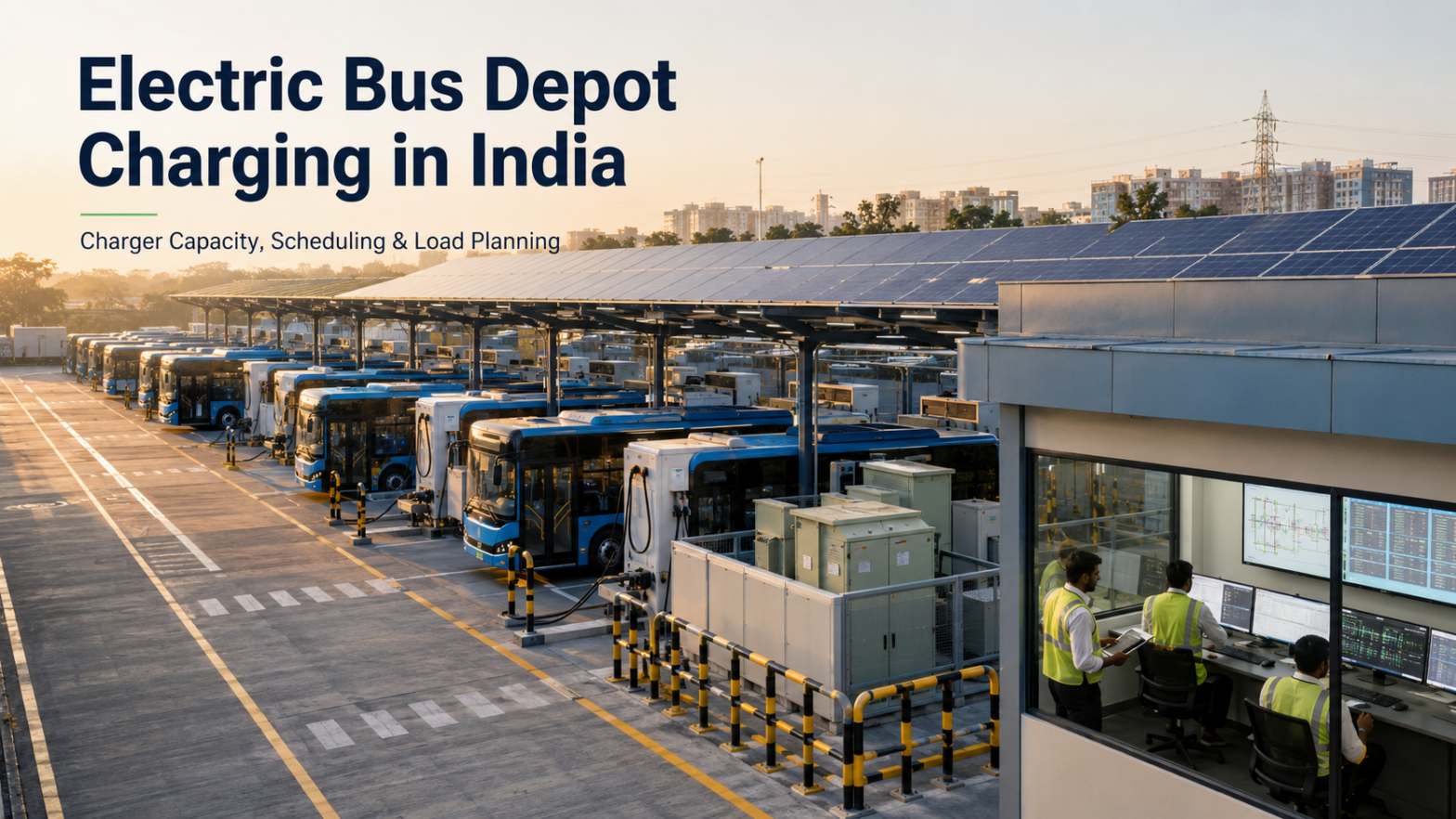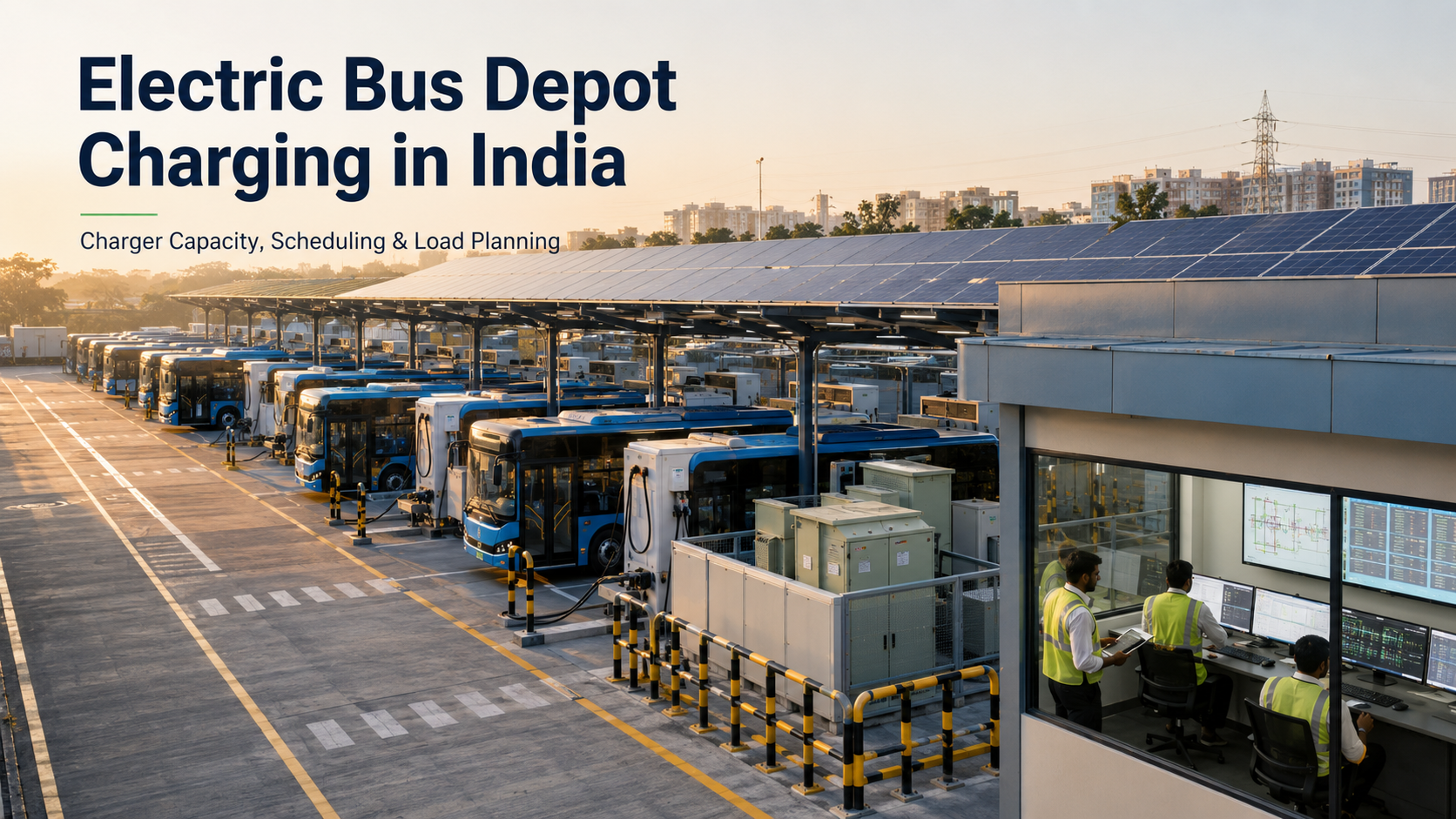
Electric buses are becoming an important part of India’s transition towards cleaner public transportation. However, purchasing electric buses is only one part of building a successful electric bus fleet.
The buses must also be charged safely, reliably and at the correct time.
Unlike a passenger car that may remain parked overnight, an electric bus usually operates according to a fixed route and timetable. A bus that has not received enough energy before its scheduled departure can disrupt services across the entire route.
An electric bus depot must therefore coordinate:
- Bus routes
- Daily travel distance
- Battery capacity
- Energy consumption
- Arrival and departure times
- Charger capacity
- Number of chargers
- Electricity connection
- Transformer capacity
- Parking arrangement
- Maintenance requirements
- Future fleet expansion
Poorly planned charging infrastructure can create extremely high peak demand, increase electricity costs and delay the grid connection required for the depot. The International Energy Agency recommends an integrated approach combining route analysis, battery sizing, charger numbers and charging schedules when planning electric bus and truck depots.
This guide explains how operators can plan an electric bus depot charging system in India that supports reliable fleet operations without unnecessarily oversizing the electrical infrastructure.
What Is Electric Bus Depot Charging?
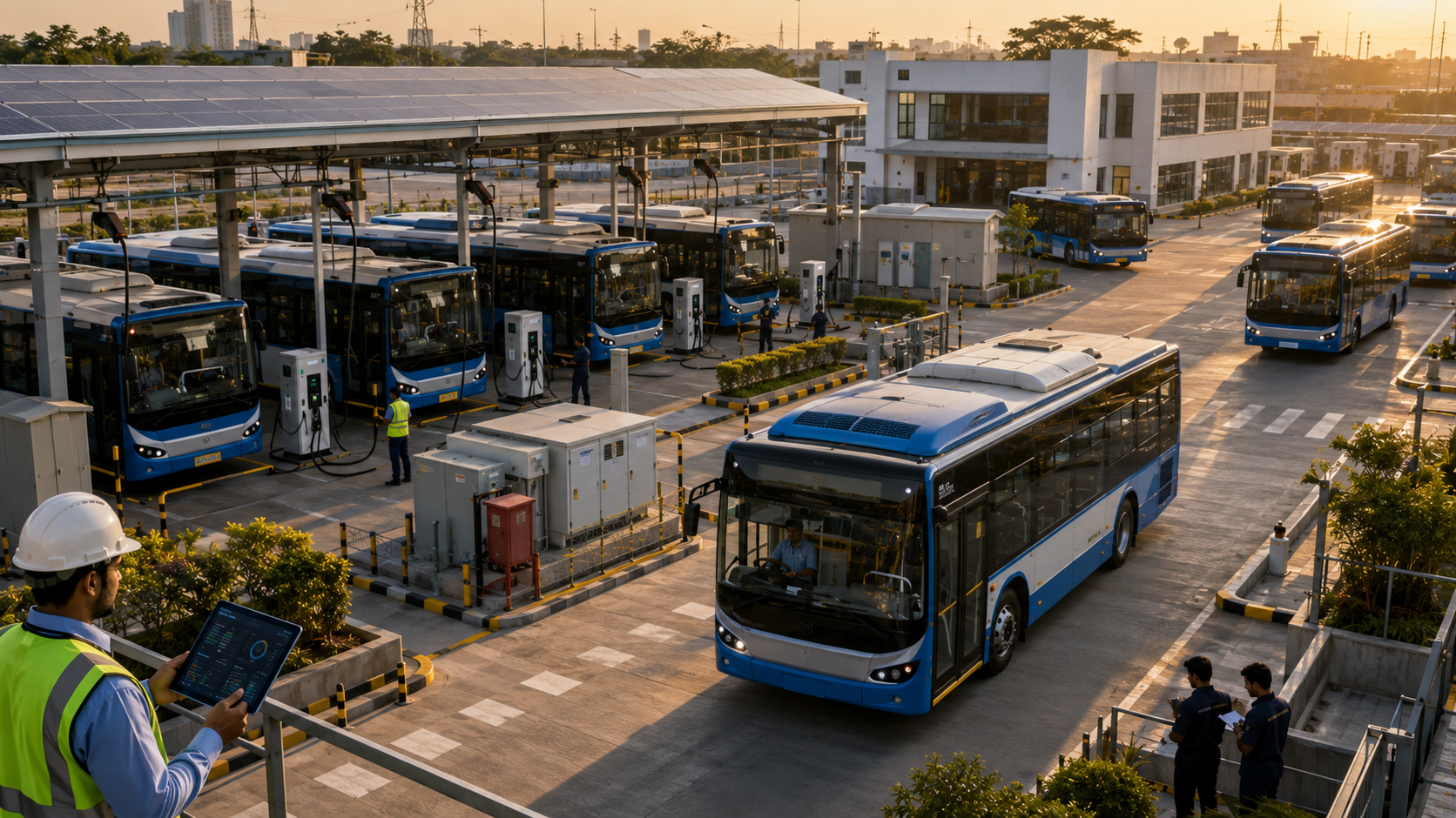
Electric bus depot charging is a charging arrangement installed at a bus parking, maintenance or operating facility.
Buses normally return to the depot after completing their scheduled routes and connect to dedicated chargers.
The charging system may operate:
- Overnight
- Between daily shifts
- During scheduled breaks
- During maintenance periods
- At selected daytime intervals
- Before the next route departure
A depot charging installation may include:
- Electric bus chargers
- Charging dispensers
- Charging cables and connectors
- Transformer
- High-tension and low-tension panels
- Electrical protection systems
- Smart meters
- Charger Management System
- Energy Management System
- Bus scheduling platform
- Solar panels
- Battery Energy Storage System
- Network and communication equipment
- Fire and electrical safety systems
A bus depot is generally considered a captive charging location because the chargers primarily serve vehicles owned or controlled by the fleet operator. India’s charging guidelines specifically recognise bus depots as captive charging facilities and apply the charging-infrastructure framework to e-bus depots.
Why Electric Bus Depot Charging Requires Detailed Planning
An electric bus has a much larger battery than most electric passenger cars.
A fleet depot may need to charge dozens or hundreds of buses within a limited operating window. When several high-power chargers run simultaneously, the depot can require a substantial electricity connection.
For example, consider a depot with:
- 50 electric buses
- 200 kWh required per bus each day
- 10,000 kWh of total daily charging energy
- A six-hour overnight charging window
Ignoring charging losses, the average charging power required would be:
10,000 kWh ÷ 6 hours = approximately 1,667 kW
The actual electrical requirement would be higher after considering:
- Charger conversion losses
- Battery charging losses
- Auxiliary systems
- Cooling equipment
- Simultaneous building loads
- Operational safety margin
If all buses are allowed to charge at maximum power immediately after entering the depot, the peak load may become much higher than the average requirement.
A properly designed charging schedule can spread the demand across the complete available window.
Main Electric Bus Charging Strategies
Electric bus fleets generally use one of three charging strategies:
- Overnight depot charging
- Opportunity charging
- Mixed charging
The correct strategy depends on the bus routes, battery capacity, available parking time and electricity infrastructure.
1. Overnight Depot Charging
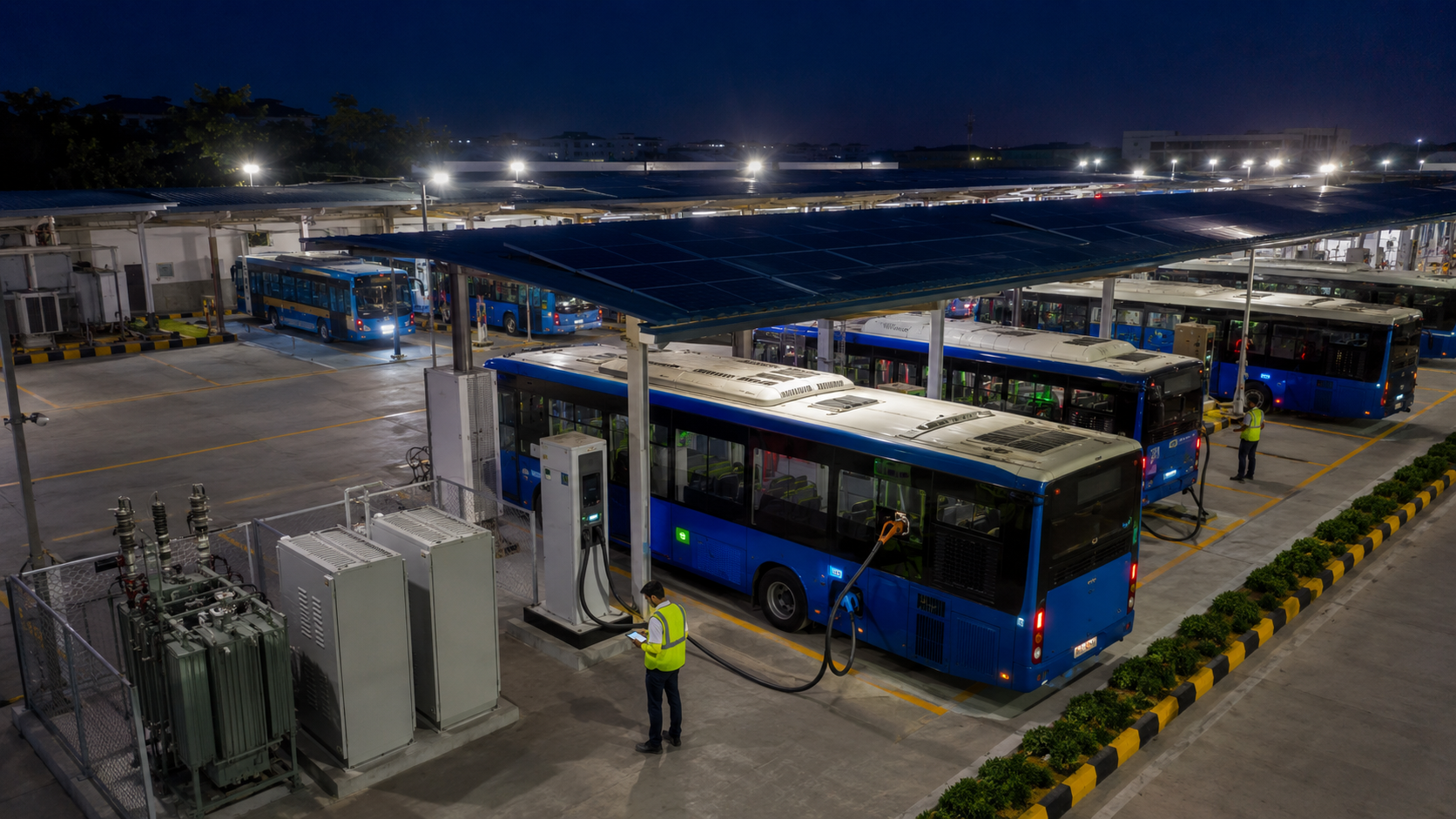
In overnight depot charging, buses complete their daily routes and return to the depot for charging.
The buses usually remain connected for several hours.
This strategy commonly uses moderate or high-power DC chargers, depending on:
- Battery capacity
- Energy required
- Time available
- Number of buses
- Depot electricity limit
Advantages of Overnight Charging
- Charging takes place at one controlled location
- Maintenance and charging can be coordinated
- Buses remain available for inspection
- Charging can be scheduled over several hours
- Lower charger power may be sufficient
- Staff can monitor the complete fleet
- Public charging infrastructure is not required
Limitations of Overnight Charging
- A large number of buses may arrive within a short period
- The depot may experience a high evening peak
- More charging points may be required
- Parking and cable management become important
- The depot may need a high-capacity transformer
- A charger failure can affect morning departures
Overnight charging is often suitable for buses that can complete their routes using one daily battery charge.
2. Opportunity Charging
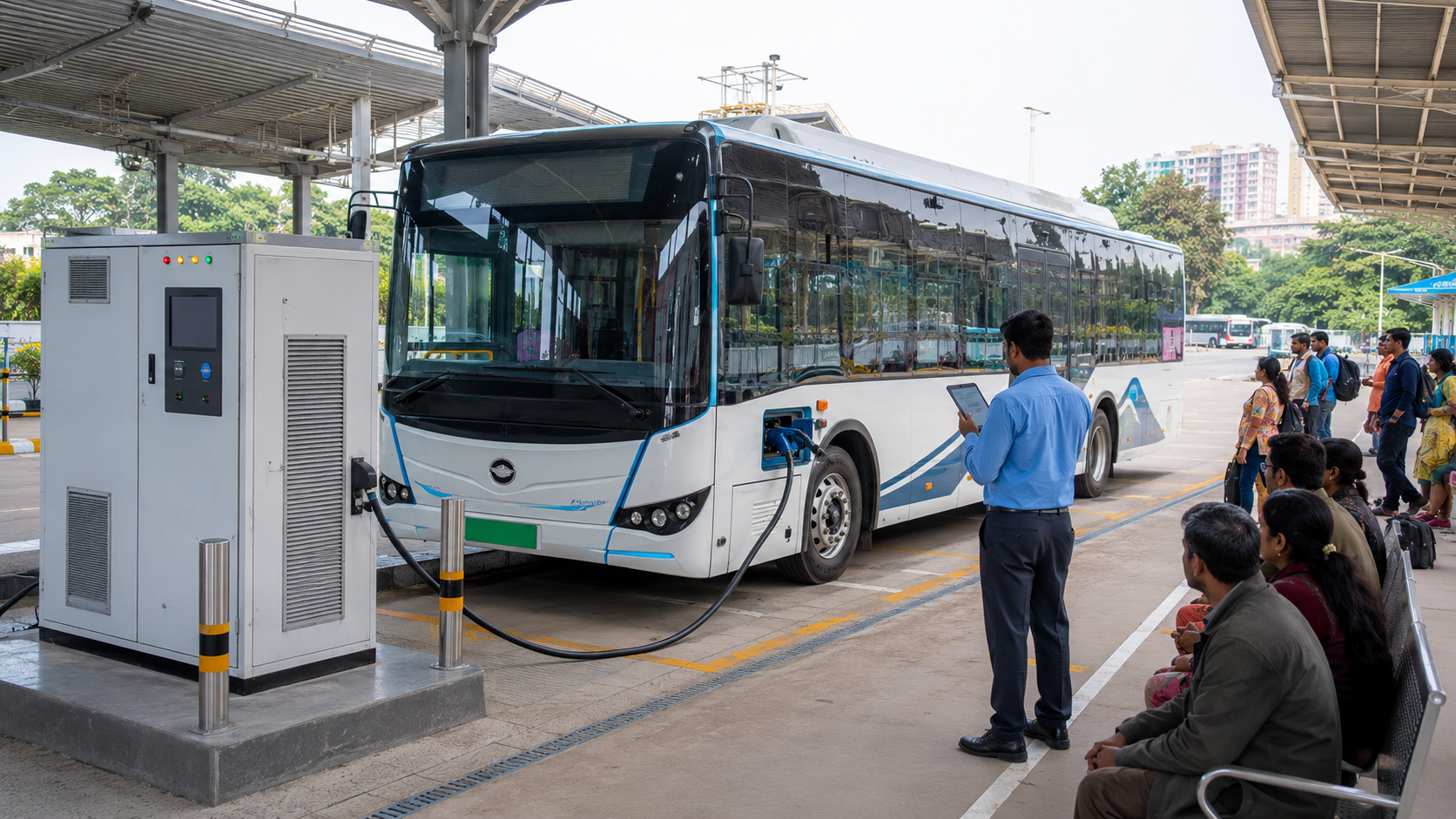
Opportunity charging provides shorter charging sessions during the operating day.
The charger may be installed at:
- Bus terminals
- Route endpoints
- Interchange stations
- Selected bus stops
- Depots between shifts
Opportunity charging normally uses higher power because the available charging time is shorter.
For example, a bus may receive additional energy during a 15-minute or 30-minute scheduled break.
Advantages of Opportunity Charging
- A bus may operate longer routes with a smaller battery
- Charging can be distributed throughout the day
- Overnight depot demand may be reduced
- Buses can receive energy between operating shifts
- Route availability may improve
Limitations of Opportunity Charging
- High-power chargers may be required
- Route schedules must remain consistent
- Charging equipment is required outside the depot
- A charger fault can directly affect bus operations
- Drivers must position buses accurately
- High daytime electricity demand may increase costs
- Additional land and permissions may be required
Opportunity charging should not be added without reviewing route reliability and expected stopping time.
3. Mixed Charging Strategy
A mixed strategy combines overnight depot charging with selected daytime charging.
For example:
- Buses receive their main charge overnight
- High-mileage buses receive an additional daytime session
- Spare buses charge during low-demand periods
- Selected routes use terminal charging
- Depot charging is reduced during peak electricity periods
A mixed strategy can reduce the required bus battery size or extend route availability.
However, it creates a more complex operating system because depot charging, route schedules and external chargers must work together.
How Much Energy Does an Electric Bus Need?
The daily energy required by a bus depends on:
- Route distance
- Passenger load
- Traffic congestion
- Road gradient
- Average speed
- Air-conditioning use
- Weather
- Driving behaviour
- Number of stops
- Battery condition
- Regenerative braking
- Auxiliary equipment
The basic calculation is:
Daily energy requirement = daily route distance × average energy consumption
Suppose a bus travels 200 kilometres per day and consumes an average of 1.2 kWh per kilometre.
The estimated daily energy requirement would be:
200 km × 1.2 kWh/km = 240 kWh
A planning margin should then be added for:
- Traffic variation
- Air-conditioning demand
- Route diversion
- Battery degradation
- Unexpected delays
- Reserve energy
- Charging losses
The actual consumption data should be collected from pilot vehicles wherever possible.
A general estimate should not replace real route data.
Understanding Bus Battery Capacity
Battery capacity is measured in kilowatt-hours.
A bus with a 300 kWh battery does not necessarily make all 300 kWh available for regular route operation.
The vehicle’s Battery Management System may maintain upper and lower reserves to:
- Protect the battery
- Reduce degradation
- Support emergency operation
- Maintain consistent performance
The usable battery capacity may also decline as the battery ages.
Fleet planning should therefore distinguish between:
- Nominal battery capacity
- Usable battery capacity
- Required route energy
- Minimum arrival state of charge
- Target departure state of charge
- Long-term battery degradation
A bus should not be scheduled using the complete theoretical battery capacity without an operating reserve.
Choosing the Correct Electric Bus Charger Capacity
The charger should be selected according to the energy required and the time available.
The basic calculation is:
Required average charging power = energy required ÷ charging time
Suppose a bus needs 240 kWh and has six hours available for charging.
The average battery input required would be:
240 kWh ÷ 6 hours = 40 kW
After accounting for charger losses and operational variation, a charger above 40 kW would be required.
A 60 kW charger may be sufficient for this example.
Now suppose the same bus has only two hours available:
240 kWh ÷ 2 hours = 120 kW
The bus would require a significantly higher-power charger.
The correct charger must also be compatible with:
- Bus connector
- Battery voltage
- Maximum vehicle charging power
- Communication protocol
- Charging curve
- Thermal limits
- Manufacturer requirements
Installing a 240 kW charger does not mean every bus can accept 240 kW.
The vehicle controls how much power it can safely receive.
Electric Bus Charger Ratings Recognised in India
India’s PM E-DRIVE operational guidelines recognise CCS-II DC chargers between 50 kW and 250 kW for electric four-wheelers, buses and trucks.
The guidelines also recognise high-power CCS-II charging between 250 kW and 500 kW for electric buses and trucks. For bus and truck projects, each charging gun is expected to provide at least 120 kW to support fast charging.
The appropriate charger rating for a depot may include:
- 60 kW
- 90 kW
- 120 kW
- 150 kW
- 180 kW
- 240 kW
- 300 kW
- 360 kW
- 500 kW
The highest available charger is not always the most economical option.
Moderate-power chargers may be suitable when buses remain parked overnight, while high-power chargers may be necessary for:
- Opportunity charging
- Short shift-change windows
- Large battery buses
- Intercity routes
- Rapid turnaround
- Emergency charging
How Many Chargers Does a Bus Depot Need?
The number of chargers does not always need to equal the number of buses.
One charger may serve multiple buses when:
- Buses arrive at different times
- Charging sessions are scheduled
- Vehicles remain parked for several hours
- Staff or automated systems move charging cables
- Chargers have multiple dispensers
- Power is dynamically shared
However, reducing the number of chargers creates operational dependencies.
The depot must consider:
- Time required to move buses
- Driver or staff availability
- Charging cable reach
- Parking arrangement
- Charger failure risk
- Morning departure sequence
- Expansion requirements
Charger-to-Bus Ratio
A charger-to-bus ratio may be expressed as:
- 1 charger for every bus
- 1 charger for every 2 buses
- 1 charger for every 3 buses
- A shared power cabinet with multiple dispensers
There is no universal ratio suitable for every depot.
A lower charger count may reduce equipment cost but increase:
- Scheduling complexity
- Cable-changing activity
- Dependence on each charger
- Risk of incomplete charging
- Bus movement inside the depot
A higher charger count can improve convenience and redundancy but may increase:
- Equipment investment
- Civil work
- Cable installation
- Maintenance cost
- Space requirements
The ratio should be determined through charging simulations using actual arrival and departure times.
Example: Calculating Charger Requirements for 30 Buses
Consider a depot with the following assumptions:
- 30 electric buses
- 180 kWh required per bus
- 5,400 kWh total daily energy
- Eight-hour charging window
- 120 kW chargers
- Approximately 90% complete charging efficiency
The approximate grid energy required would be:
5,400 kWh ÷ 0.90 = 6,000 kWh
The average charging power required across eight hours would be:
6,000 kWh ÷ 8 hours = 750 kW
If the depot installs ten 120 kW chargers, the maximum combined charger rating would be:
10 × 120 kW = 1,200 kW
However, the depot does not necessarily need to draw 1,200 kW throughout the night.
A smart charging system could limit the total EV charging load to approximately 800 kW or another approved value and distribute it among the connected buses.
Each charger could serve three buses during the night when the schedule provides enough time for cable changes and bus movement.
This example is illustrative. A real design must account for individual bus arrival times, battery states, departure schedules and charging curves.
Understanding Simultaneous Charging Demand
The maximum charger rating and the actual depot demand are not always the same.
A depot may have:
- Twenty 120 kW chargers
- A theoretical combined rating of 2,400 kW
- A controlled charging limit of 1,500 kW
The Energy Management System can prevent all chargers from drawing their maximum power simultaneously.
Power may be allocated according to:
- Bus departure time
- Current state of charge
- Energy required
- Route importance
- Charger availability
- Transformer capacity
- Electricity tariff
- Solar generation
- Battery storage output
This approach can reduce the depot’s maximum electrical demand without reducing fleet readiness.
Role of Smart Charging and Scheduling

Smart charging is essential for a large electric bus depot.
A Charger Management System can communicate with the chargers, while a fleet or Energy Management System uses operational information to control charging.
The system may consider:
- Bus identification
- Assigned route
- Arrival time
- Departure time
- Battery state of charge
- Required departure state of charge
- Charger availability
- Electricity capacity
- Electricity tariff period
- Maintenance status
The system can then determine which buses should charge first.
Priority-Based Bus Charging
Not every bus needs the same priority.
A charging schedule may assign higher priority to:
- Buses leaving earliest
- Buses assigned to long routes
- Buses with low battery levels
- Buses required for peak-hour services
- Buses replacing unavailable vehicles
- Emergency or essential routes
A bus scheduled for departure at 4:30 AM should normally receive charging priority over a bus departing at 9:00 AM.
Sequential Charging
Sequential charging allows different groups of buses to charge at different times.
For example:
- Group A charges from 9:00 PM to midnight
- Group B charges from midnight to 3:00 AM
- Group C charges from 3:00 AM to 6:00 AM
This can reduce the number of chargers and control the maximum power demand.
The schedule must include enough time for:
- Vehicle movement
- Cable connection
- Charging delays
- Charger faults
- Maintenance activity
Dynamic Power Sharing
Dynamic power sharing distributes the depot’s available electricity among active chargers.
Suppose a depot has a charging limit of 1,000 kW and ten buses are connected.
The initial allocation may be:
1,000 kW ÷ 10 buses = 100 kW per bus
If two buses complete charging, their available power can be redistributed among the remaining vehicles.
The system may also provide:
- 150 kW to buses leaving early
- 80 kW to buses leaving later
- Reduced power to nearly full batteries
- No power to buses already meeting their route requirement
Electricity Infrastructure Required for an E-Bus Depot
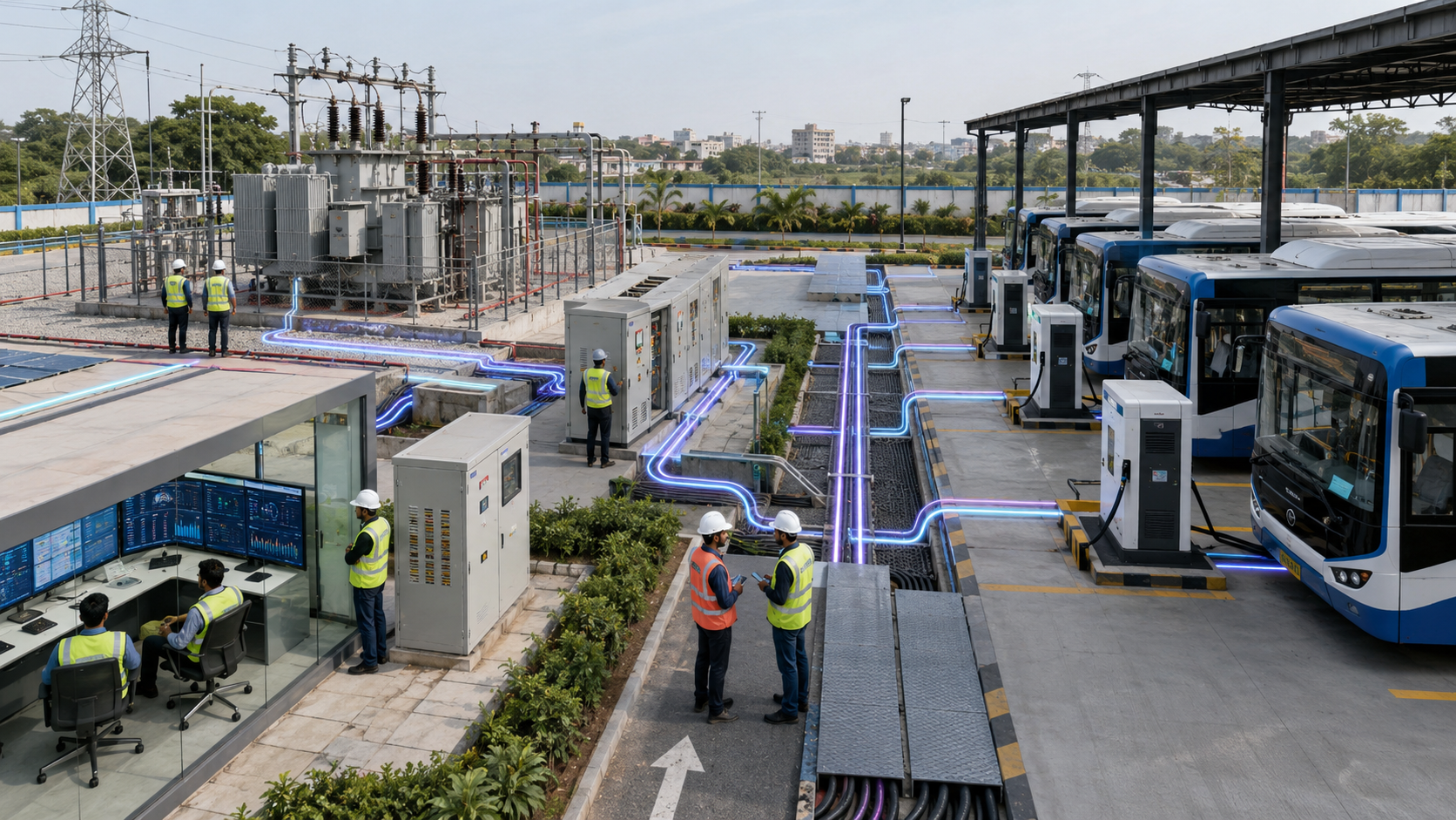
Electric bus charging can create megawatt-level demand.
The depot may require:
- High-tension electricity connection
- Dedicated distribution transformer
- Ring Main Unit
- High-tension panel
- Low-tension panel
- Circuit breakers
- Protection relays
- Electrical isolators
- Bus ducts
- High-capacity cables
- Smart metering
- Earthing system
- Lightning protection
- Emergency shutdown
- Power Management System
The final design should be approved by qualified electrical professionals and coordinated with the relevant electricity distribution company.
Estimating the Depot’s Electrical Load
The electrical-load assessment should include:
EV Charging Load
This is based on the number of chargers and controlled simultaneous demand.
Workshop Load
The maintenance area may contain:
- Lifts
- Air compressors
- Diagnostic equipment
- Welding systems
- Pumps
- Cleaning equipment
Building Load
The depot may require electricity for:
- Offices
- Lighting
- Ventilation
- Air conditioning
- Security
- Staff facilities
Auxiliary Charging Systems
Additional equipment may include:
- Charger cooling
- Battery storage cooling
- Communication systems
- Control rooms
- CCTV
- Fire systems
Future Expansion
The electrical design should consider the expected increase in:
- Number of buses
- Battery capacity
- Charging power
- Workshop activity
- Depot operating hours
Planning only for the first batch of buses may create expensive reconstruction later.
Transformer Planning
The transformer should not be selected simply by adding the maximum rating of every charger.
The design should consider:
- Controlled simultaneous demand
- Charger efficiency
- Building load
- Workshop load
- Power factor
- Harmonic performance
- Safety margin
- Future expansion
- Redundancy requirements
A single large transformer may reduce initial complexity, but multiple transformers can provide greater operational flexibility.
For example, a depot may divide the charging installation into separate electrical zones. If one transformer or electrical section is unavailable, some chargers may continue operating.
Grid Connection Timeline
A high-capacity electricity connection may take longer to arrange than the charger installation itself.
The process may involve:
- Load application
- Site survey
- Feasibility approval
- Transformer planning
- High-tension connection
- Network reinforcement
- Metering approval
- Electrical inspection
- Energisation
Grid planning should begin early in the bus procurement process.
Waiting until buses are ready for delivery can result in vehicles arriving before the depot can charge them.
The Ministry of Power framework gives State Nodal Agencies responsibility for coordinating with DISCOMs and regulatory bodies to facilitate electricity connections for public, workplace, community and e-bus depot charging stations.
Electric Bus Depot Layout Planning
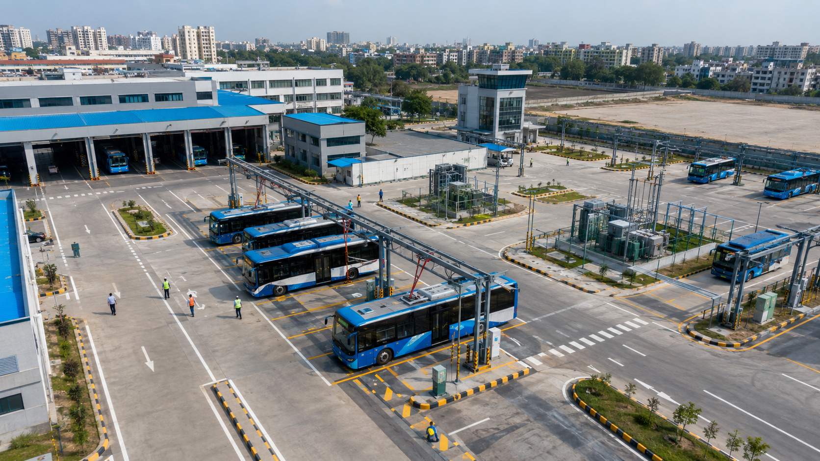
The depot layout affects both charging efficiency and operational safety.
Important layout considerations include:
- Bus entry and exit
- Parking direction
- Charger positioning
- Cable reach
- Turning radius
- Pedestrian movement
- Maintenance access
- Transformer area
- Electrical room
- Fire access
- Drainage
- Equipment protection
- Future expansion
Charger Positioning
Chargers may be installed:
- At the front of each parking bay
- Between two parking bays
- Along a central charging lane
- On overhead structures
- Inside a protected power room with external dispensers
The charging port position on the selected bus model must be confirmed before finalising the depot layout.
A charger installed on the wrong side may create:
- Cables crossing vehicle lanes
- Trip hazards
- Difficult bus positioning
- Cable damage
- Longer civil works
- Unsafe operations
Cable Management
High-power bus charging cables can be heavy.
The depot may use:
- Cable retractors
- Overhead cable supports
- Floor-mounted cable guides
- Suspended cable systems
- Protected cable channels
Charging cables should not remain in areas where they can be:
- Driven over
- Crushed
- Stretched
- Exposed to standing water
- Damaged by workshop activity
Vehicle Movement
The charging layout should minimise unnecessary bus movement.
Frequent repositioning can increase:
- Staff requirements
- Charging delays
- Risk of minor collisions
- Energy consumption
- Operational complexity
Where possible, a bus should enter the depot, park, charge and leave without requiring repeated repositioning.
Maintenance and Charging Coordination
Some buses may require scheduled maintenance after completing their route.
The depot should decide whether the bus will:
- Charge before maintenance
- Charge during maintenance
- Charge after maintenance
Maintenance activities should not block charging access or create unsafe work near energised equipment.
Chargers should also remain accessible for technicians without requiring several buses to be moved.
Redundancy and Charger Availability
A depot should not assume that every charger will be available every day.
Chargers may become unavailable because of:
- Preventive maintenance
- Cable damage
- Connector damage
- Communication failure
- Power-module fault
- Software update
- Electrical isolation
- Vehicle collision
- Network interruption
The charging plan should include spare capacity.
Possible approaches include:
- Additional standby charger
- Spare charging gun
- Modular power cabinets
- Ability to move a bus to another bay
- Emergency public charger agreement
- Mobile charging support
- Reserved charging time
A depot designed with no redundancy may experience route cancellations after a single charger failure.
Charger Management System for Bus Depots
A Charger Management System should provide more than basic charger monitoring.
Useful functions include:
- Real-time charger status
- Bus identification
- Charging-session control
- Remote start and stop
- Dynamic power adjustment
- Fault alerts
- Energy reporting
- Charging history
- Firmware management
- User permissions
- Maintenance records
- Electricity-cost reporting
The platform should preferably integrate with the fleet scheduling system.
This allows charging decisions to be based on actual bus operations rather than only charger availability.
Data Required for Intelligent Charging
The system may use the following information:
- Bus registration or fleet number
- Route assignment
- Planned departure time
- Planned return time
- Battery state of charge
- Required departure charge
- Battery temperature
- Charger capacity
- Charger availability
- Electricity limit
- Energy tariff
- Solar output
- Battery storage level
Accurate data improves charging reliability.
Incorrect departure times or battery information may cause the system to prioritise the wrong bus.
Communication Standards
Open communication protocols can support charger monitoring and integration.
The charging platform may use:
- OCPP for communication between chargers and the management platform
- APIs for fleet scheduling integration
- Smart-meter communication
- Energy Management System communication
- Bus telematics data
The system should also include appropriate cybersecurity protection, secure user access and verified software updates.
Solar Energy for Electric Bus Depots
Bus depots often have large roofs and parking areas that may be suitable for solar panels.
Solar systems may be installed on:
- Workshop roofs
- Office buildings
- Parking canopies
- Maintenance sheds
- Dedicated ground-mounted areas
Solar energy can help supply:
- Daytime bus charging
- Depot building load
- Workshop equipment
- Battery storage
However, solar panels alone are unlikely to provide the complete power required by a large bus depot.
A one-megawatt charging load cannot be supported continuously by a relatively small rooftop solar installation.
Solar should be integrated with:
- Grid supply
- Smart charging
- Battery storage
- Energy Management System
Battery Energy Storage for Bus Depots
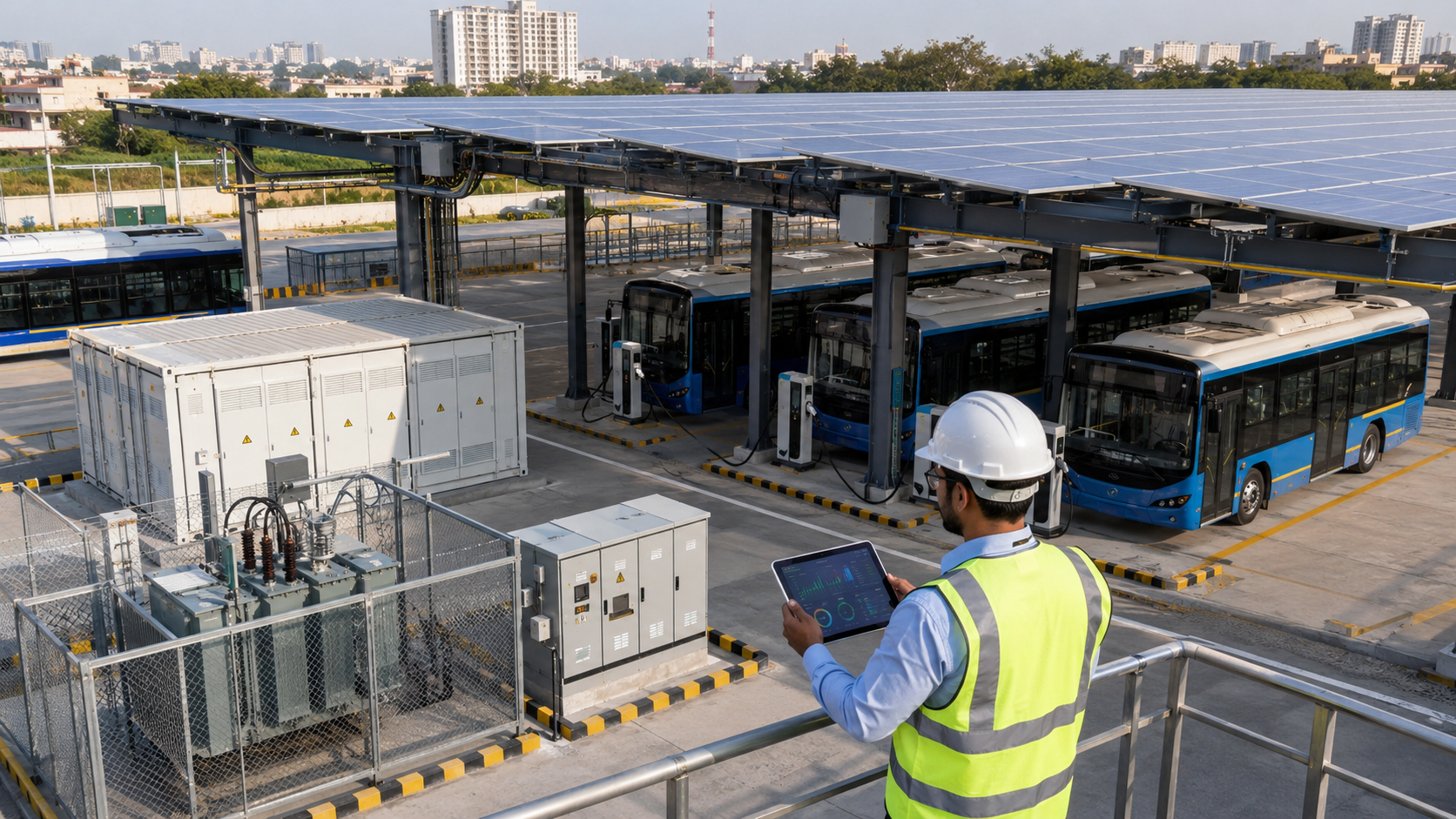
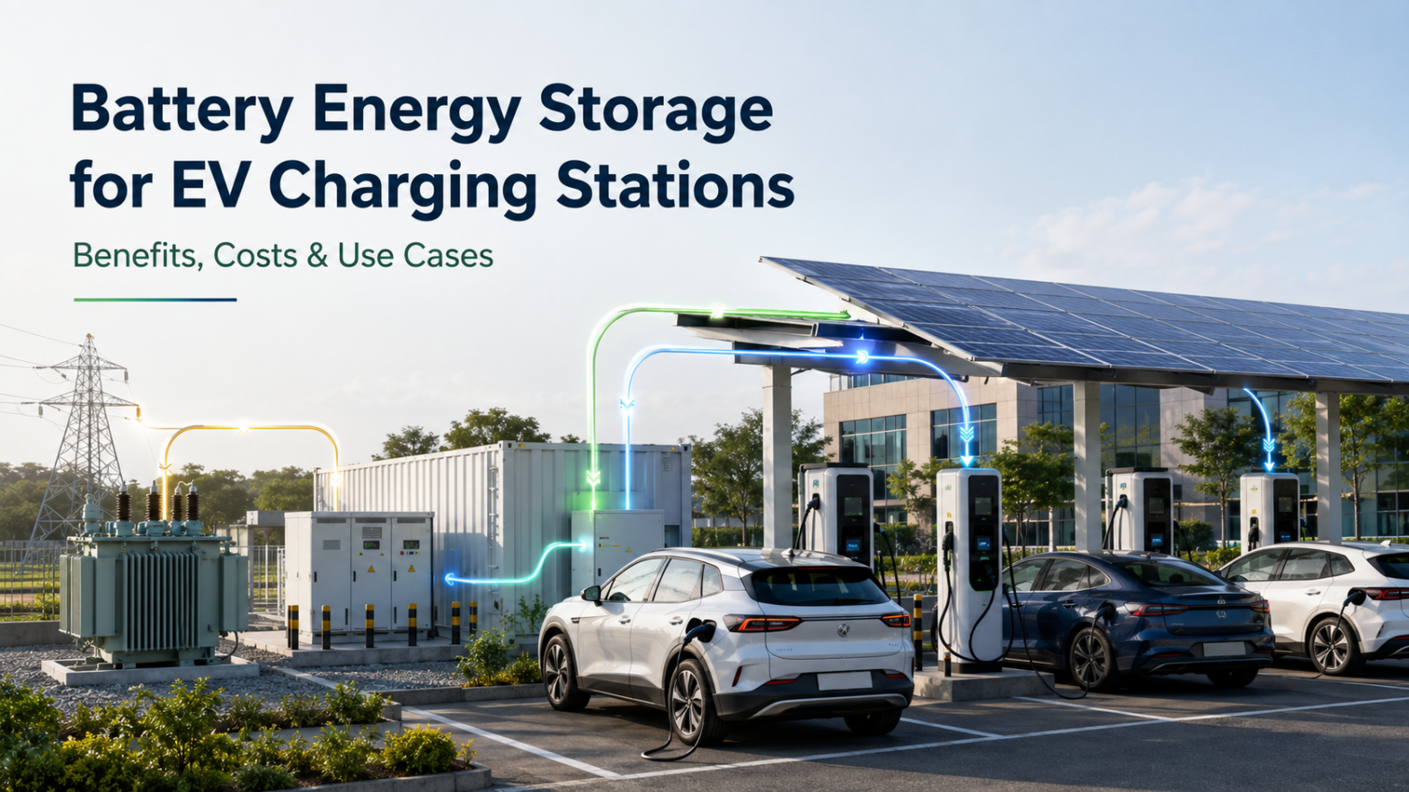
A Battery Energy Storage System can store electricity and release it when bus charging demand increases.
It may help:
- Reduce temporary grid peaks
- Store daytime solar energy
- Support short high-power charging periods
- Reduce demand during selected tariff periods
- Improve resilience for essential systems
Battery storage should be evaluated carefully because electric bus depots require large amounts of daily energy.
A small BESS may support short peaks but may not be capable of charging the complete fleet during a grid failure.
The project should compare:
- Grid-upgrade cost
- BESS installation cost
- Battery degradation
- Electricity savings
- Solar utilisation
- Required backup duration
- Expected charging peaks
Can a Bus Depot Operate During a Power Outage?
A conventional grid-connected charging depot may stop charging during a power outage.
A BESS or generator can support selected loads, but backup capacity must be planned according to operational requirements.
Critical loads may include:
- Charging control systems
- Network equipment
- Security
- Lighting
- Emergency systems
- Selected bus chargers
Providing full backup for dozens of high-power chargers would require a very large system.
The operator should define:
- Which routes are essential
- Which buses must remain available
- Required backup duration
- Minimum emergency charging power
- Alternative charging locations
Safety Requirements for Electric Bus Charging
Electric bus depots combine high-voltage equipment, large vehicles, batteries and frequent staff movement.
Safety planning should cover:
- Electrical isolation
- Earthing
- Circuit protection
- Emergency shutdown
- Fire detection
- Fire suppression
- Equipment ventilation
- Water drainage
- Vehicle impact barriers
- Restricted electrical zones
- Warning signs
- Staff training
- Emergency response
- Charger inspection
Electrical Safety
Only trained and authorised staff should access:
- High-tension panels
- Transformers
- Charger power cabinets
- Distribution panels
- Battery storage equipment
Electrical rooms should remain locked and protected from unauthorised access.
Fire and Emergency Planning
The depot should coordinate with qualified fire and safety professionals.
The emergency plan should include:
- Charger isolation
- Bus isolation
- Staff evacuation
- Fire-service access
- Emergency contact details
- Damaged-battery handling
- Vehicle movement restrictions
- Post-incident inspection
Emergency routes should not be blocked by parked buses or charging cables.
Protection Against Vehicle Impact
Chargers, electrical panels and battery storage should be protected from accidental bus impact.
Possible protection measures include:
- Bollards
- Crash barriers
- Raised equipment platforms
- Wheel stops
- Marked clearance zones
The barriers should protect equipment without blocking maintenance access.
Water and Drainage
Charging equipment should not be installed in areas where water can accumulate.
The site should consider:
- Monsoon rainfall
- Drainage slope
- Flood level
- Water used for bus washing
- Roof runoff
- Cable trenches
Bus washing areas should be separated appropriately from charging and high-voltage equipment.
Staff Training
Drivers and depot staff should be trained to:
- Connect and disconnect chargers correctly
- Inspect cables before use
- Report damaged connectors
- Recognise fault indicators
- Use emergency shutdown controls
- Avoid driving while connected
- Follow charging-bay rules
- Respond to unusual heat, smell or sound
Technical staff should receive additional training for charger maintenance and electrical isolation.
Charging During Solar and Off-Peak Hours
The depot may reduce electricity costs by scheduling charging during preferred tariff periods.
However, electricity tariffs differ by state, electricity connection and distribution company.
The charging strategy should evaluate:
- Energy charge
- Demand charge
- Time-of-day tariff
- Solar-hour tariff
- Fixed charges
- Power factor penalties
Charging only during the lowest-cost period may not be practical when buses have early departures.
Fleet readiness should remain the first operational priority.
Calculating the Cost of Charging an Electric Bus Fleet
A simplified electricity-cost calculation is:
Charging cost = electricity consumed from the grid × applicable electricity tariff
Suppose the depot imports 6,000 kWh each day at an average effective rate of ₹8 per kWh.
The estimated daily electricity cost would be:
6,000 kWh × ₹8 = ₹48,000
The monthly cost for 30 operating days would be:
₹48,000 × 30 = ₹14,40,000
The actual cost may also include:
- Demand charges
- Fixed charges
- Taxes and duties
- Power factor charges
- Metering charges
- Solar adjustments
- Battery storage losses
Operators should use actual tariff orders and electricity bills for financial planning.
Performance Indicators for an Electric Bus Depot
The depot should monitor both charging and fleet performance.
Important indicators include:
- Total daily energy delivered
- Energy consumed per bus
- Energy consumed per kilometre
- Peak depot power demand
- Average charging power
- Charger utilisation
- Charger uptime
- Successful charging-session rate
- Number of missed charging sessions
- Buses ready at departure time
- Charging cost per bus
- Charging cost per kilometre
- Energy loss
- Transformer loading
- Charging faults
- Average maintenance response time
Bus Readiness Rate
One of the most important indicators is the percentage of buses that meet their required state of charge before departure.
A charger network may show high uptime but still fail operationally when the wrong buses are charged first.
The system should therefore measure whether every scheduled bus was ready at the correct time.
Charger Utilisation
Charger utilisation helps determine whether the depot has:
- Too many chargers
- Too few chargers
- Poor scheduling
- Excessive idle time
- Uneven charger use
Very low utilisation may indicate overinvestment.
Extremely high utilisation may leave no room for delays, maintenance or fleet expansion.
Energy Consumption per Kilometre
Tracking energy consumption per kilometre can identify:
- Inefficient routes
- Driver behaviour
- Heavy air-conditioning use
- Battery deterioration
- Vehicle faults
- Unusual passenger loads
The information can improve route planning and future bus procurement.
Charger Maintenance
Electric bus chargers require regular inspection and preventive maintenance.
The maintenance programme may include:
- Visual inspection
- Connector inspection
- Cable inspection
- Cooling-system check
- Filter cleaning
- Electrical tightening
- Earthing test
- Insulation test
- Emergency-stop test
- Software updates
- Communication test
- Power-module performance check
Maintenance should be scheduled during periods when the charger is least likely to affect bus departures.
Spare Parts Planning
The depot should maintain or arrange rapid access to important spare parts, such as:
- Charging connectors
- Charging cables
- Communication modules
- Cooling components
- Power modules
- Contactors
- Fuses
- Display components
Waiting several days for a basic spare part can reduce the available fleet.
Steps for Planning an Electric Bus Depot
Step 1: Collect Route Data
Record:
- Daily distance
- Trip frequency
- Passenger loading
- Road gradient
- Traffic conditions
- Average speed
- Break duration
- Depot arrival time
- Departure time
Step 2: Estimate Daily Energy Demand
Calculate the expected energy required for each route and add an operating reserve.
Use pilot-bus data whenever available.
Step 3: Select the Charging Strategy
Decide whether the fleet will use:
- Overnight charging
- Opportunity charging
- Mixed charging
Step 4: Determine Charger Capacity
Calculate the power required according to:
- Bus energy requirement
- Available charging time
- Vehicle charging limit
- Future expansion
Step 5: Simulate Charging Schedules
Create a schedule showing:
- Bus arrival
- Charger assignment
- Charging start
- Charging completion
- Departure requirement
Test the schedule under:
- Normal operations
- Late bus arrivals
- Charger failure
- Power restriction
- Higher energy consumption
- Maintenance activity
Step 6: Calculate Maximum Electrical Demand
Determine the controlled simultaneous charging load rather than only adding every charger rating.
Include building and workshop loads.
Step 7: Coordinate With the DISCOM
Begin the electricity-connection process early.
Confirm:
- Available network capacity
- Connection voltage
- Transformer requirements
- Metering
- Approval timeline
- Tariff category
Step 8: Finalise the Depot Layout
Confirm charger positions, electrical rooms, cable paths, vehicle movement and safety access.
Step 9: Select Chargers and Software
Evaluate:
- Bus compatibility
- Charger power
- Connector
- OCPP support
- Dynamic load management
- Remote monitoring
- Warranty
- Service support
- Spare parts
Step 10: Install and Test the System
Test:
- Every charger
- Every bus model
- Load management
- Power failure recovery
- Communication failure
- Emergency shutdown
- Scheduled charging
- Full fleet operations
Step 11: Train Depot Staff
Train drivers, charging staff, maintenance personnel and control-room operators.
Step 12: Monitor and Optimise
Review actual charging and route data regularly.
Adjust charger priorities and power limits as the fleet grows.
Government Support for Electric Bus Charging
India’s PM E-DRIVE scheme includes support for electric buses and charging infrastructure.
The official scheme information provides for procurement support for 14,028 electric buses by State Transport Undertakings and public transport agencies. It also proposes support for 1,800 fast chargers for electric buses.
Charging projects must meet the applicable technical, procurement and implementation conditions.
Fleet operators and infrastructure providers should verify the latest scheme notifications, nodal-agency processes and tender requirements before making investment decisions based on expected financial support.
Common Electric Bus Depot Planning Mistakes
Purchasing Buses Before Confirming the Electricity Connection
The buses may arrive before the depot is capable of charging them.
Selecting Chargers Only by Maximum Power
Higher charger power increases electrical demand and may not provide value when buses remain parked overnight.
Ignoring Real Route Energy Consumption
Published battery specifications cannot replace actual route testing.
Installing One Charger for Every Bus Without Scheduling Analysis
This may unnecessarily increase equipment and infrastructure costs.
Installing Too Few Chargers
Excessive charger sharing may create cable changes, bus movement and missed departures.
Ignoring Charger Failure
The depot should have enough redundancy to continue critical routes.
Planning Only for the Initial Fleet
Cable routes, transformers and parking layouts should consider future expansion.
Separating Fleet Scheduling From Charging Management
The charging system must know when each bus is required.
Ignoring Cable and Bus-Port Position
Incorrect charger placement can create unsafe cable paths and difficult parking.
Depending Completely on Solar Energy
Solar generation varies and may not match overnight charging demand.
Treating Battery Storage as Unlimited Backup
A BESS provides a limited amount of stored energy and must be recharged.
Ignoring Staff Training
Even a technically advanced system may fail when charging procedures are not followed consistently.
Questions to Ask an Electric Bus Charger Supplier
Before selecting chargers, ask:
- Which bus models are compatible?
- What voltage range is supported?
- What is the maximum continuous power?
- Is the rated power per gun or shared?
- Does the charger support dynamic power sharing?
- Which connector standard is used?
- Which OCPP version is supported?
- Can the charger integrate with fleet software?
- Is remote monitoring included?
- What is the expected charger efficiency?
- How is cable cooling maintained?
- What warranty is provided?
- What uptime commitment is available?
- Are spare parts stocked in India?
- What is the response time for service?
- Can additional power modules be added later?
- What cybersecurity controls are included?
- What happens during internet failure?
- Can charging continue safely in offline mode?
- What preventive maintenance is required?
Is Depot Charging Suitable for Every Electric Bus Fleet?
Depot charging is particularly suitable when:
- Buses return to a central location
- Routes are predictable
- Vehicles remain parked for several hours
- A suitable grid connection is available
- Charging can be centrally managed
- Maintenance occurs at the same facility
Opportunity charging may be required when:
- Routes exceed practical battery range
- Buses have short overnight parking periods
- Rapid turnaround is necessary
- Terminal stops provide sufficient charging time
Many fleets may benefit from combining both strategies.
The final decision should be based on total operating cost, service reliability and infrastructure availability.
Conclusion
Electric bus depot charging requires coordinated planning across transport operations, vehicle batteries, charger capacity and electricity infrastructure.
The most powerful charger or largest transformer does not automatically create the most effective depot.
A successful electric bus charging system should:
- Supply enough energy for every scheduled route
- Ensure buses are ready before departure
- Control peak electricity demand
- Use chargers efficiently
- Provide redundancy for equipment failures
- Support future fleet expansion
- Maintain safe vehicle and staff movement
- Integrate fleet and charging data
- Provide reliable maintenance support
Before installing chargers, operators should analyse route distance, bus energy consumption, arrival and departure schedules, grid capacity and the complete depot layout.
Planning an electric bus depot charging project? Contact Earthtron EV to evaluate charger capacity, electrical infrastructure, charging schedules and future fleet-expansion requirements.